Corner Relief In Sheet Metal Catia

Catia Sheetmetal Design Corner Relief Youtube
Catia Generative Sheetmetal Design Corner Relief Cut Out Youtube

Catia V5 Corner Relief Sheet Metal Youtube

Pin On Solidworks

Pin On Art

Solidworks Surface Modeling Creating A K Blend Surface Modeling Solidworks Surface

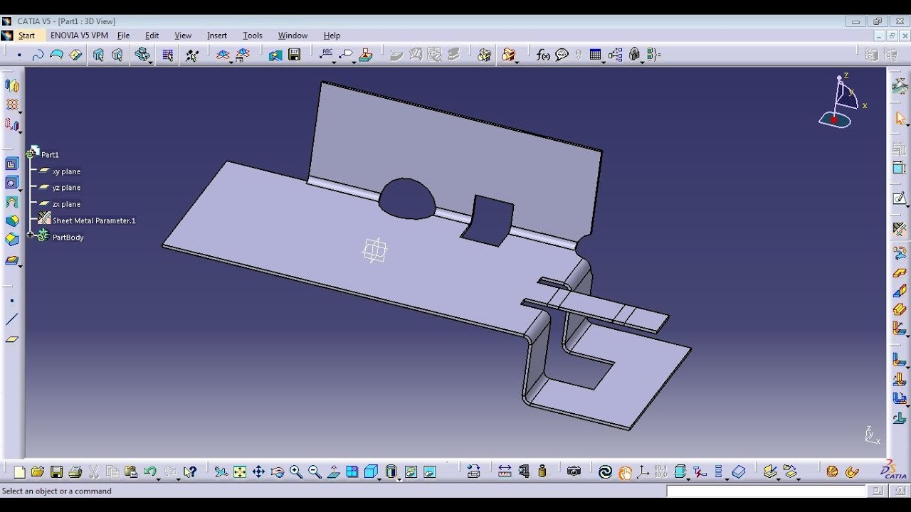
Through this course the user will be able to learn catia v5 sheet metal design.
Corner relief in sheet metal catia.

How To Create A Corner In Catia V5 Youtube

Catia Generative Sheet Metal Design Cutting Stamping Toolbar Youtube

How To Fill Corner Gaps On Sheet Metal Parts Bricscad Mechanical Youtube

Solidworks Sheet Metal Tutorial Forming Tool Youtube Solidworks Solidworks Tutorial Sheet Metal Drawing

Solidworks Tutorials Q A How Do I Create A V Shaped Sheet Revit

Solidworks Sheet Metal Youtube In 2020 Solidworks Tutorial Solidworks Tutorial

Youtube Sheet Metal Tools Sheet Metal Metal Tools

Catia V5 Sheetmetal 09 Extrude Cutouts Rib Flanged Hole Youtube

Solidworks Tutorial Sketch Kitchen Sink In Solidworks Kitchen Tools Sketch Solidworks Tutorial Sketch Kitchen Sink In Solidworks In 2020 Organizer Tricks Sinken

Solidworks Tutorial Corner Treatment Sheet Metal Tutorial Youtube

Youtube Solidworks Metal Working Sheet Metal
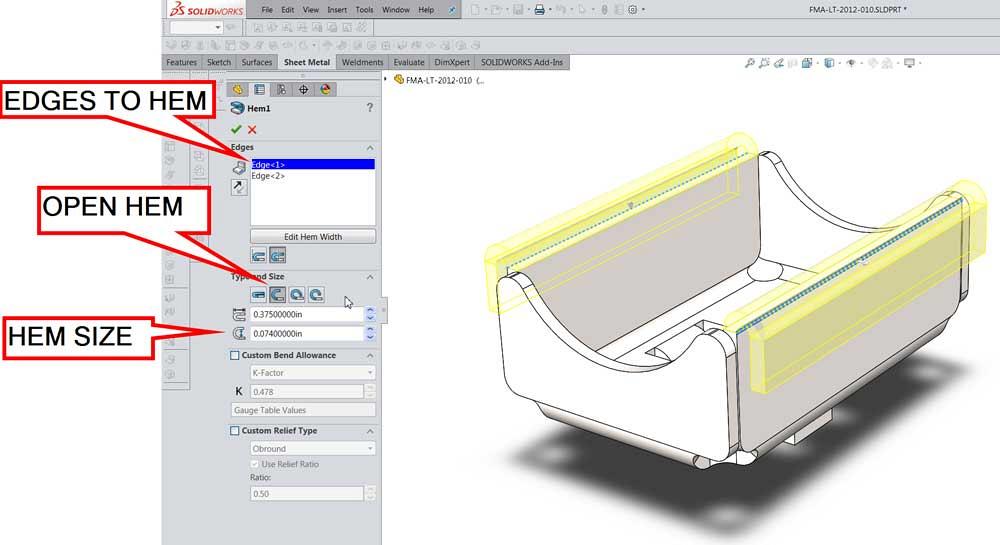
Sheet Metal Tips And Tricks

Hem Feature Design Guidelines In Sheet Metal Design Sheet Metal Metal Sheet Design Sheet Metal Drawing

Pin On Solidworks

Solidworks Sheet Metal Lofted Bend Youtube Sheet Metal Drawing Solidworks Sheet Metal

Solidworks Sheetmetal Close Corner Weld Corner Corner Relief Chamfer Fillet Hindi Urdu Youtube

Sheet Metal Corner Relief Tools Cad Design Tools Youtube

Free Sheet Metal Unfold Software

Bend Order In Solidworks Sheet Metal Parts Solidworks Sheet Metal Solid Works
What Sheet Metal Shops Wish You Knew Hems Jogs And Forming Tools

Freecad Sheet Metal Manual Youtube

Importing Sheet Metal Using Convert To Sheet Metal
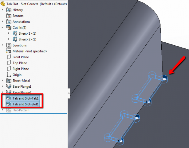
What S New In Solidworks 2019 Sheet Metal Slot Corners

Throwback Thursdays Sheet Metal
Source : pinterest.com
